I Don't Know Why.
But these two posts seem to have (eventually, finally) broken this blog's Google Search ranking. I don't know why or how, but the dreaded "Alternative page with proper cano(I'm going to break the word here in just in case)nical tag" error appeared. (No, I had no idea what that meant. I'm not an SEO wonk. It took me an hour of Googling to find out wtf was going on and I still don't really know...)
Apparently it means two of my pages are "cano------nical" versions of one another sort of thing. Now mind you, this blog is on Blogspot.com, a Google property. It does all manner of stuff with my content and spits out a blog page. Whether it decides one version of something in "canon----ical" or not is magic mirrors to me. I certainly don't go whacking (<link rel="cano---nical" href="https://somedamnpage.okay?"> links into the html of the page because I never get to see that html.
Since I have no control over what Google's pieces of - regrettable code - shoved into those pages, I've decided to put both posts together into a new post and delete the original posts. Can't throw an error if the pages are deleted... Deleting them removes the possibility that somehow Google Search was reading a title as a link rel cano-etc. Stupid as that may sound, I'm out of other ideas.
Secondly, I'm also going to go through the body text of both posts and edit the cano-word in case Search had that in it's sights. MANUALLY, because the blogger (blogspot) editor doesn't allow search/replace.
Here (re-)goes:
The Adventure Continues
I've finally printed the draft X - Y motion components I started to mention in this past article. It's a bit stressful here due to some health concerns so I've been doing this more as a way to keep myself occupied than as a serious push to make the machine.
Anyhow - back to the bits. I've designed with cheaply obtainable parts in mind such as four wheel gantry plates, 2020 V slot, and PLA. To make my cunning plans I've also printed at 50% infill and 4 walls rather than the 100% / 4 I'll use for the finished thing.
I'm also only using 300mm lengths of 2020 because that'll still give around 180x180x(??? Not sure on Z capacity yet but between 40mm and 60mm should be possible) and I don't want too much 'give' in the structure.

So since I only printed one Y carriage / gantry post, I can only give an approximation of what I hope will be. The post is printed in three parts because it fits more easily on most printer beds that way, and seems to be pretty solid under the loads I've been able to put on it.
As you can see, the gantry plate runs outside the Y rail. Due to the width of the carriages on the X rails, that space wouldn't be available as work surface anyway, so may as well compact the machine and also reduce the leverage the gantry carriage can exert. Anyway - first, the three parts of the post:
- Lower carriage (S Carriage) holds the 4wheel carriage plate and lifts the rest of the post up to a useful distance. It can be printed thicker, wider, but preferably not taller so it can be printed on more printers.
- Upper carriage (CarriageExtn) brings us up to the height needed.
- Gantry Rail Plate (GantryPlate) goes inside and does two things, it bolts together and stiffens the other two parts, and it has sockets at various locations that the end of a 2020 will fit snugly in.
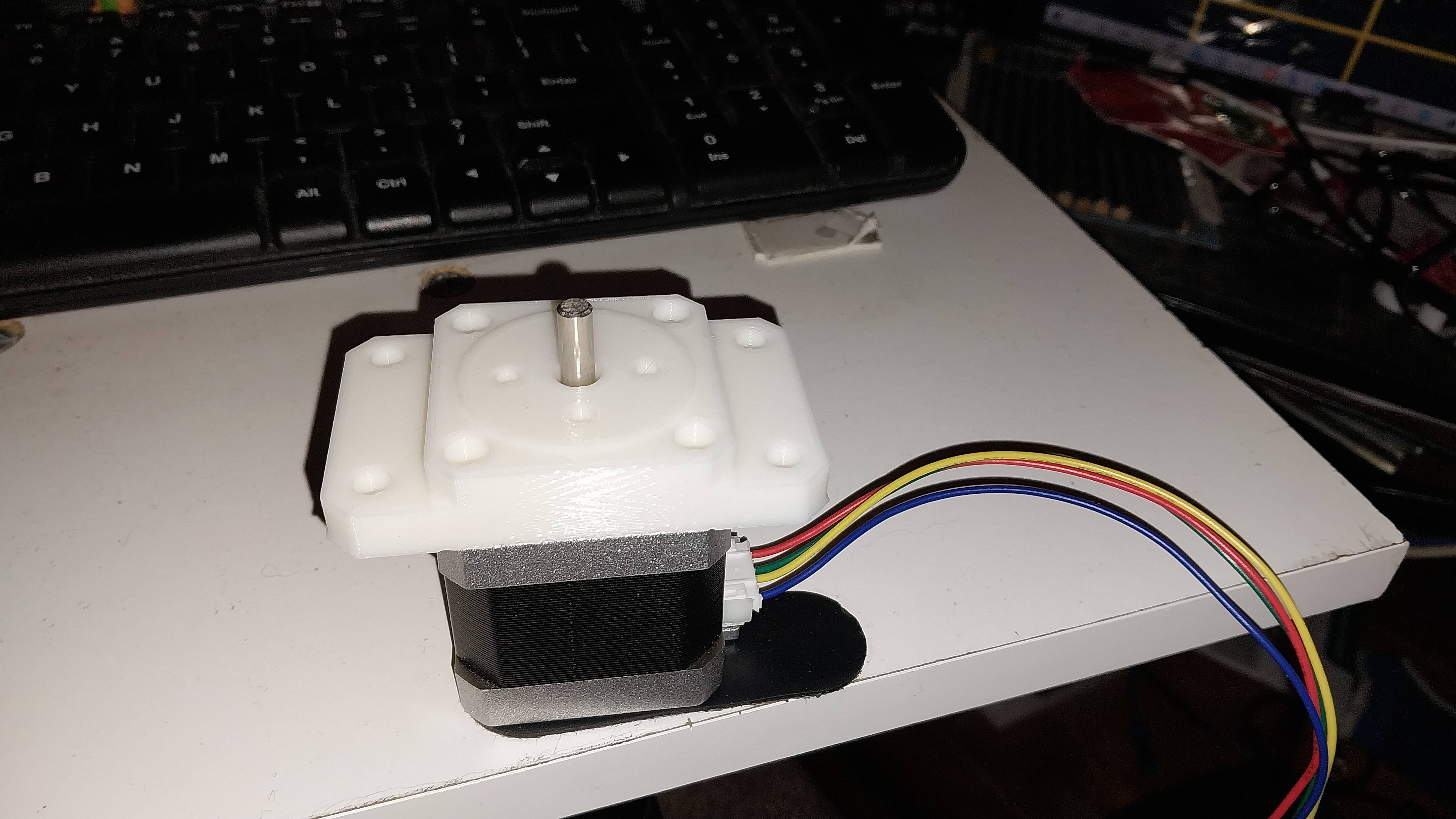
Eventually, a bracket for a NEMA17 stepper motor will be included in the final print, for now I still need to work out how I want that to go.
You'll see four sockets, at this stage they were semi-randomly laid out because I didn't have a 4wheel plate to get exact measurements. There are two sockets side by side at the top and ditto around 110mm lower. The further apart I can get them vertically, the heavier a spindle I can mount here without twisting in the fore-aft direction due to the angular pressure when lowering the tool onto the work.
Having them left and right means you can print the same GantryPlate for either side. And by placing the rails off to one edge, that also means that the angular pressure transmitted down to the Y carriages is less because the spindle will be more centred.
The plan is to find the best vertical distance between the two X rails so that the two 4wheel plates can be joined together with some kind of simple aluminium plate that can be manufactured with simple hand tools. (Because I don't have a CNC to machine them yet. . .) The spindle elevator slider will then get mounted onto that.

Things that still need to be designed and done.
I can now come up with some logical distance between the X rails so that standard spindle slides can be used.
I can slightly widen the posts for a bit more strength. The X axis stepper motor can be mounted on one Upper Carriage Ext'n and a pulley on the other with holes for a 6mm T2 timing belt to go through to move the spindle carriage. I'm thinking of once again raiding AliExpress for two angle plates designed for that purpose and preferably able to use the same mounting holes for simplicity. (So that there needs only be one patter for Upper Carriage Ext'n.) While inexpensive, this is still coming out of my pension so when you see the links below to subscribe to the newsletter and maybe also donate one-time or a regular patronage, please consider it. . .
I'll design and print a mounting post that can go at each of the Y rails and fix them to the wooden machine base, with all the bits needed to mount another NEMA17 and some way to get it to drive both sides in sync, so either two servos in parallel or a solid axle and second set of gear.
A mount for the GRBL board, manual control panel, and power supply will come in handy.
Design decisions, why.
I know that a lot of designs move the bed in the Y direction à la 3D printer, and that does make it far more simple for the Y direction. But I'm up for the challenge (😹 he said, weeping furiously at his bravado and arrogance) and also this does allow me to apply two stepper motors if I need the extra grunt.
Using PLA was a conscious decision too, not just what I had to hand. Comparisons between PLA and PETG and ABS show that modern PLA is up there with ABS in strength, and as I said I've 'designed' (and I use that term negligently and frivolously) this to eliminate pressure from the tool to the plastic so we'll see how good I was.
6mm T2 belts. Yeah. This may become one of the first things that has to be upgraded. But I've seen Ivan use belts on some really big machines and they seem to be very accurate and repeatable, and I've seen what abuse a 6mm belt can survive when things went wrong on the Ender3 Pro . . .
Everything being cheap. This is one of my design aims. The aluminium 2020 extrusion was very cheap, and looks lightweight. Hence my desire to reduce stresses on it too. One other result though was that the hole down the middle was a 5mm hole. Generally they're 3mm or 4mm but if you're extruding ali and make that hole bigger then that's a smidgen of material you save per metre...
That turned to an advantage for me because I could tap it to 6mm and so get a much stronger bolt holding things together. So when you get to yours, either drill it out to 5mmm or tap to the size you have and use thinner hardware.
You may know that I'm hoping to start a website for people to get into plastic recycling at home and on the cheap, not so much because I think it'll stem the tide of plastics but because it'll raise awareness of just how much of this shit we still use without a qualm. So this has to be able to be made by a guy with old guy eyesight and manual dexterity, on a pension, and then be readily able to make whatever's needed for the recycling project.
On that subject.
I started looking at plastic recycling after watching a few of Dave Hakkens' Youtube videos on Precious Plastic which is now on the One Army channel. So I may even go to their website with my machines and so forth, not sure yet. At least it'll get some coverage there.
But as I went along, I discovered that recycling plastic isn't the ultimate goal. Public awareness is. Taking plastic out of the waste stream for a second, third, fourth, and subsbequent life - that is. Because if we can keep some of it out of the waste stream for a few more years, several things will happen:
- Because people will start demanding that their products are delivered in recycled plastics, or in some other packaging that's biodegradeable.
- Governments will start clamping down on making 'virgin' plastic, which is plastic made from petrochemicals. Corporations are going to find it cheaper to finally bite the bullet and take their crap back and recycle it.
- And other people like myself and maybe yourself will start developing technology to recover plastic out of the environment, recycle it, or break it down cleanly and safely.
The upshot though will be that free range plastics in the environment will decrease.
My other thought on that subject.
So why the CNC machine? My hope is that once a person gets involved they, just like me, will want to do other recycling. Aluminium is the second-most commercially recycled metal on Earth after lead. (I think I recall seeing that somewhere.) But it's also easy to smelt aluminium at home with some basic gear and a lot of care and caution. And aluminium can be milled flat and then used to make molds for injection molding . . .
Once you can use injection molding you can turn a whole lot of waste plastic into identical products at speed. (i.e. if you wanted to make promotional items or money-making products, this is a quick way to do so.)
And once you're comfortable with that, you can also machine a new print head for your printer that can used pelletised recycled plastic, or a recycling tool to make filament for your printer from recycled plastics.

Footer
So please support me. If you can, take a look at my News Stand where you'll see live updated links to everything I publish; or take a subscription to my weekly newsletter where you'll receive the same information in your inbox for free; Or contact me via the webform or directly email me if you'd like to help; or donate either directly or at my Ko-Fi page for the price of a coffee. Or even make a regular monthly donation there. (Check why you should donate here.)
----------------------------------------------------------------
CAN_CNC New Working Title
Thanks go to Canon for making a printer I couldn't use any parts from, ultimately. So now CANO----Nical_CNC has had to become CAN_CNC and I'm kind of glad to use those Canon parts for a laser engraver or something later on. For now I'd like CAN_CNC to get to the point of being a real desktop CNC with enough grunt to cut (or at least mangle) aluminium so I'll be able to make plastic injection molds.
I started with a draft mode print, horrible layer heights, only 2 walls, 20% infill and some blue PLA made by XingTongZhiLian and obtained from Amazon a while back. Just as well because the first drafts used a fair chunk of the spool, despite looking like this:

Even that first print consisting of three parts (print bed size limitations) showed right away that there wasn't enough stability in the lower carriage alone to prevent movement. Needs two carriages, possibly even spaced 50mm apart to provide that kind of mechanical advantage. Also, there was a fit issue between the two tower parts. The first draft stood for ages as the only work to be done, before I got a second wind a week ago.
Made With Tinkercad.
Yep. I humbly admit that I am a total fumble-arse when it comes to CAD software, and because I started with Second Life building, Tinkercad is a lot more knowable to me. "Start with a prim . . ." works for me and I could build quite well. TC is missing a few features like making solids physical i.e. you can't drop a cube on top of another cube, which is sometimes handy.
Also, using TC leaves a LOT of conjoined parts and sometimes they create odd issues within an .STL. So my plan is to do as I'm doing now and make a lot of draft models first, then replicate each part once I have the final bugs ironed out. I've used this in the past, but a 30min draft print using 20g is a far cry from a 5hr 120g sort of print, that's one tenth of a spool and A) I HATE wasting plastic and B) I really can't afford to recycle it (YET!!!) and C) I can't really afford to throw away filament because I don't sell anything to cover the cost.
So parts I make are constrained a bit, but as I gain skill with TC and dial in my TC to RL capability this'll improve and so will the parts. But for now, the second drafts are good for honing my skills.
Second Draft.

So the second draft has proven really useful. I've spotted a few gotchas and indicated them on that image above. First though, a quick tour of Ca _cNc. (That's "CAN_CNC" with white ant holes for making a slightly lighter and faster print. . .)
ALSO: I know the filament looks really P I N K ! ! ! but it's actually a purplish colour in real life, it just seems to defeat the white balance on any cameras I've photographed it with.
We're looking at the left hand tower from the left. Just a bit up and to the left of D is a bushing block for the Y rail that the towers will run back and forwards on. At the moment this is on the floor but there are two blocks that those bushes will attach to, and that'll lift it another 40mm or so. I didn't bother to print those yet because I need to work from the spindle and tool backwards so that I can make sure it'll carry the weight without any give. Looking like a big ask at the moment but I'll get there.
Now to the points:
A: Around the motor mount, things are really tight. I stepped the top section out at this point to let the X rail extrusions sit aft of the centre of the Y carriage (more on this later) and it's good, but I added all sorts of internal means for stiffening this joint and they're all crap, whereas the stepped-out section is great but could actually be made longer and all the smart-assery with joint stiffeners can be eliminated and that'll make it more rigid too. And leads to:
B: See that mis-matched join? That's why the join bits need to go, this side too needs to be stepped out, and the overlap made longer.
C: This curvy edge is great but needs serious stiffeners. As you can see there's a little stiffener from lower right up and to the left that I cut for lightweighting the draft but even if it were there, it won't have the necessary oomph to hold a 400W 30,000rpm router spindle. Luckily I can add a bit more meat here in the next (and hopefully last) draft.
D: It's in orange as it isn't a bug, not really. I just didn't attach the second set of carriage wheels as I need to stretch the lower section by another 20 - 30mm as I've decided the Y rails will need to just be 400mm to give me room for more stabilising length.
A further thing is that I still haven't designed a suitably tough belt tensioning mechanism for the other ends of the X and Y - Y belts.
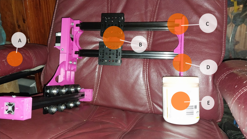
This is a better view, Just orange dots here, A: yep we have cats and yep they have no respect for nice things, so we don't have nice things but instead have cats, which are better anyway.
B: I haven't worked out the spindle slide yet but may have to just buy one. Some more on the balance of the X carriage (told you there'd be more) is needed here. The spindle motor and slider will need to sit on those two 4-wheel plates and the centre of the motor (and hence the tool) would have sat forward of the CoG (centre of gravity) of the smaller (remember the blue draft?) tower, and that means that it would have sagged forward at rest and been pushed backwards when the tool makes contact with the work and pushes up.
Moving the X rails back and widening the base of the tower puts the centre of the spindle motor and most of the weight right in between those two 4-wheel plate carriages at the base of the tower. And that means all the fore and aft wobble in the tower will only come about from moving fore and aft, not from the motor and tool weight nor from the force the tools transmits back.
C: These 2020 bushes take up some travel room but also provide some left-right stability, and note the notch in the front faces, these are a feature of both X and Y bushes and allow the belt stopper to slip in and save a few mm of travel. There's also an inverted vee brace that will go from the bottom of the left hand tower to the upper X rail and down to the right hand tower, I won't print this but instead use cheap perforated zinc plated hardware straps from the local hardware and a spacer, which will stop L-R wobble.
There may also be a second set of braces from the lower 2020 rail. They'll each require a tee nut inside the vee groove at the rear of the rail, a spacer to allow the carriage wheel axles to pass, and then the two hardware straps down to mounts on the left and right towers.
D: Still on these two X rail bushes and blocks, a few further mods - have to slightly rework them to strengthen them, make them also project downwards a bit longer for stiffness, and that's about it, they're the second part of this build I'm satisfied with. Oh okay - E: - that's not really the right-hand side of the CNC, it's a jar of sunshine aka vitamin D. It just means I'm happy with progress so far.
End of this stage.
From here on it's going to be a case of iterate and progress. All parts will become much simplified because I'll build each one anew for versions b3.0a onwards. All parts now have a path to final form with just a few redrafts, and then I'll decide a filament to use. Not the material, I'm sticking to PLA, but a colour scheme and where I'll buy it from.
Okay - here are a few more pics.
 |
| The first blue draft helped a lot to shape the second. |
This piece now has a new future as a brass insert setter and PCB drill, it's actually quite strong. I'll print a base for it that'll allow use as either.
Thanks go to anyone that's been thinking of supporting me, now would be the perfect time to head to my Paypal link or even to Ko-Fi.com to make a donation or monthly donation (much like another craftsman support platform but with less of the membership going to the platform than Patreon) and helping out and you'll get a mention as the first ten monthly patrons and first ten donors, and a spot on the CNC somewhere will bear the first ten monthly supporters' names.
Also take a look at everything, or just take out a news letter, it's once a week so it won't flood your inbox.


No comments:
Post a Comment